
UVM stands for Universal Verification Methodology. It is a SystemVerilog-based framework used to build reusable, scalable and coverage-driven testbenches for ASIC, FPGA, intellectual property, subsystem and system-on-chip verification.
Modern semiconductor designs are too complex to verify through a collection of isolated, manually written tests. A contemporary SoC may integrate processors, memories, interconnects, accelerators, security controllers, peripheral interfaces and third-party IP. Each block may work correctly by itself while unexpected interactions still produce failures at subsystem or system level.
Verification teams therefore need more than a simulator or programming language. They need a structured method for:
- Generating stimulus
- Driving hardware interfaces
- Monitoring design behaviour
- Predicting expected results
- Checking actual results
- Measuring functional coverage
- Reusing verification components
- Managing regression and closure
UVM provides this structure.
It defines recognised verification components, communication mechanisms, simulation phases, configuration methods and reusable development patterns. This gives engineers a consistent architecture for building complex simulation environments and makes it easier to transfer verification knowledge and IP between projects.
UVM is widely used within professional design verification services because it supports systematic functional verification while remaining flexible enough for different protocols, design types and project scales.
UVM at a Glance
| Question | Answer |
| What does UVM stand for? | Universal Verification Methodology |
| What is UVM used for? | Building reusable hardware verification testbenches |
| What language does UVM use? | SystemVerilog |
| Is UVM a programming language? | No. It is a methodology and class library |
| What does a UVM testbench contain? | Sequences, sequencers, drivers, monitors, agents, scoreboards, environments and tests |
| Where is UVM used? | IP, ASIC, FPGA, processor, subsystem and SoC verification |
| Does UVM replace formal verification? | No. Simulation and formal verification are complementary |
What Does UVM Mean in SystemVerilog?
UVM is not a separate programming language. It is a class library and verification methodology implemented using SystemVerilog.
SystemVerilog supplies the language features required to create the verification environment, including:
- Classes and objects
- Inheritance and polymorphism
- Constrained randomisation
- Interfaces
- Queues and dynamic arrays
- Covergroups
- Assertions
- Tasks and functions
UVM builds on these capabilities by providing standard base classes such as:
- uvm_test
- uvm_env
- uvm_agent
- uvm_sequencer
- uvm_driver
- uvm_monitor
- uvm_scoreboard
- uvm_sequence
- uvm_sequence_item
The difference is straightforward:
| SystemVerilog | UVM |
| Provides the verification language | Provides the testbench methodology |
| Supports classes and constraints | Defines reusable verification components |
| Supports covergroups | Organises coverage collection |
| Supports interfaces | Uses virtual interfaces to access DUT signals |
| Supports assertions | Integrates assertions into a wider verification strategy |
| Can be used without UVM | Requires SystemVerilog |
Engineers who are new to class-based verification should first understand SystemVerilog concepts such as objects, inheritance, interfaces, randomisation and constraints. Alpinum’s SystemVerilog Training supports these foundations before engineers progress to full UVM development.
Why Was UVM Created?
Before standard verification methodologies became widely adopted, many engineering teams developed internal testbench frameworks.
These could solve immediate project requirements but often created longer-term problems:
- Components were difficult to reuse.
- Testbenches used inconsistent structures.
- Verification IP required extensive integration work.
- Tests became tightly coupled to particular designs.
- Engineers had to learn a new framework for every project.
- Debugging and reporting approaches varied between teams.
- Moving between simulators could require substantial rework.
UVM established common terminology, component roles, communication methods and execution phases.
This does not make every UVM testbench identical. Projects still require design-specific stimulus, checking, coverage and configuration. However, an engineer familiar with UVM should recognise the overall architecture of another UVM environment even when the DUT, protocol, company and simulator differ.
What Is a UVM Testbench?
A UVM testbench is a class-based verification environment built around a Design Under Test, commonly called the DUT.
The DUT may be a small RTL block, reusable IP, FPGA design, processor, subsystem, ASIC or complete SoC.
A typical stimulus path is:
Test → Sequence → Sequencer → Driver → DUT
The observation and checking path is:
DUT → Monitor → Reference Model, Scoreboard and Functional Coverage
This separation is one of the most important UVM principles.
The component that generates or drives stimulus should not normally decide whether the DUT response is correct. Independent monitoring and checking reduce the risk of repeating the same incorrect assumption in both the stimulus and expected-result logic.
The Main Components of a UVM Testbench
UVM Test
The test is the top-level class that selects and configures a verification scenario.
It may:
- Configure the environment
- Select active or passive agents
- Apply factory overrides
- Choose sequences
- Enable coverage
- Configure error injection
- Define protocol parameters
- Manage test completion
Teams often create a reusable base test and derive specialised tests for reset recovery, protocol compliance, stress, security, low-power operation or error handling.
UVM Environment
The environment contains the principal verification components.
Depending on the project, it may include:
- One or more agents
- Scoreboards
- Reference models
- Coverage collectors
- Register models
- Virtual sequencers
- Protocol checkers
- Configuration objects
A small IP environment may contain one agent and one scoreboard. A subsystem or SoC environment may integrate many agents and several checking paths.
UVM Agent
An agent packages components associated with a particular DUT interface.
An active agent normally contains:
- Sequencer
- Driver
- Monitor
A passive agent monitors activity but does not drive the interface.
Agents support reuse because the same protocol component may be integrated into several projects. An AXI, APB, SPI, UART or proprietary-interface agent can potentially be reused at IP, subsystem and SoC level.
UVM Sequence Item
A sequence item is a transaction object.
Instead of describing each signal transition, it represents an operation at a higher level of abstraction.
A bus transaction may contain:
- Address
- Data
- Read or write direction
- Burst length
- Delay
- Protection attributes
- Response information
A packet transaction may include source, destination, payload, priority and error fields.
Constraints can restrict transaction fields to legal or strategically important combinations.
UVM Sequence
A sequence creates one or more sequence items.
A sequence may represent:
- A single transfer
- A burst of operations
- A reset and configuration flow
- An error condition
- A traffic pattern
- A complete system use case
Sequences are reusable because they operate at transaction level rather than directly manipulating DUT signals.
UVM Sequencer
The sequencer controls the delivery of sequence items to the driver.
It can:
- Receive requests from sequences
- Arbitrate between multiple sequences
- Supply transactions to the driver
- Return responses where required
The sequencer does not normally drive signals itself.
What Is a Virtual Sequencer in UVM?
A virtual sequencer coordinates activity across several interface-level sequencers.
For example, a subsystem test may need to configure registers through APB, generate traffic through AXI and wait for an interrupt from another interface. A virtual sequence can coordinate these operations through a virtual sequencer.
Virtual sequencers are valuable in multi-agent environments, but they should not be introduced unnecessarily. Additional coordination layers can make execution and debugging harder to follow.
UVM Driver
The driver converts transaction-level requests into signal-level activity.
A sequence item might define an address, data value and operation type. The driver translates this information into the clock-by-clock handshaking required by the protocol.
A well-designed driver should:
- Follow the protocol accurately
- Handle reset correctly
- Report configuration errors clearly
- Avoid implementing checking that belongs elsewhere
- Remain reusable across suitable environments
Virtual Interface
UVM components are class-based, while the DUT consists of static SystemVerilog signals.
A virtual interface connects these two domains.
The driver uses it to control signals, while the monitor uses it to sample them. The physical interface is generally instantiated in the top-level module and passed to the UVM environment through configuration.
UVM Monitor
The monitor passively observes DUT activity.
It samples interface signals, reconstructs completed transactions and publishes them to components such as:
- Scoreboards
- Reference models
- Coverage collectors
- Protocol checkers
- Performance analysers
Because the monitor is independent of the driver, it can observe traffic generated by the UVM testbench, embedded software, another hardware block or external verification IP.
UVM Scoreboard
The scoreboard determines whether DUT behaviour is correct.
It may compare:
- Actual and predicted output
- Input and output transactions
- Received and transmitted packets
- DUT behaviour and a reference model
- Register contents and expected values
- Transaction ordering and architectural rules
Some scoreboards perform simple in-order comparisons. Others must handle variable latency, multiple outstanding operations, out-of-order completion or packet reordering.
Useful scoreboard messages should explain what failed, where it failed and which transaction caused the mismatch.
Reference Model
A reference model predicts expected DUT behaviour.
It may be written in SystemVerilog, C, C++, Python, MATLAB or another suitable language.
The model should be sufficiently independent of the RTL. Recreating the RTL implementation line by line in another language risks reproducing the same conceptual error rather than providing an independent expected result.
Functional Coverage Collector
Functional coverage measures whether important features, combinations and conditions have been exercised.
It may track:
- Transaction types
- Address ranges
- Configuration modes
- Error conditions
- State transitions
- Privilege levels
- Interrupt scenarios
- Cross-coverage between related features
Coverage should be derived from the verification plan and design requirements. A high percentage is meaningful only when the coverage model represents genuine design intent.
Alpinum’s guide to verification planning and coverage closure explains how requirements, tests, assertions, checkers and coverage should remain connected.
UVM Register Abstraction Layer
The UVM Register Abstraction Layer, or UVM RAL, provides an object-oriented representation of memory-mapped registers and memories.
It can model:
- Registers and fields
- Addresses
- Access permissions
- Reset values
- Address maps
- Memories
- Mirrored values
RAL supports register reads, writes, reset checking, access-policy testing, register coverage and front-door or back-door access.
How Does a UVM Testbench Work?
A simplified UVM workflow follows eight steps.
1. Configure the Environment
The test defines agent settings, interface parameters, protocol options, coverage requirements and sequence selection.
2. Create Transactions
A sequence creates directed, randomised or constrained-random sequence items.
3. Manage Transaction Delivery
The sequencer controls how transactions reach the driver.
4. Drive the DUT
The driver converts transactions into interface-level signal activity.
5. Observe Behaviour
The monitor independently reconstructs completed transactions.
6. Predict Expected Results
A reference model produces the expected DUT response where required.
7. Check Results
The scoreboard compares observed and expected behaviour.
8. Measure Coverage
Coverage collectors record which planned features and conditions occurred.
Regression failures and coverage gaps then guide the next activity. Engineers may refine constraints, add targeted sequences, improve checking, investigate RTL defects or update the verification plan.
This creates a coverage-driven verification process rather than a disconnected collection of tests.
What Are UVM Phases?
UVM phases define the standard lifecycle for building, connecting, running and closing a verification environment.
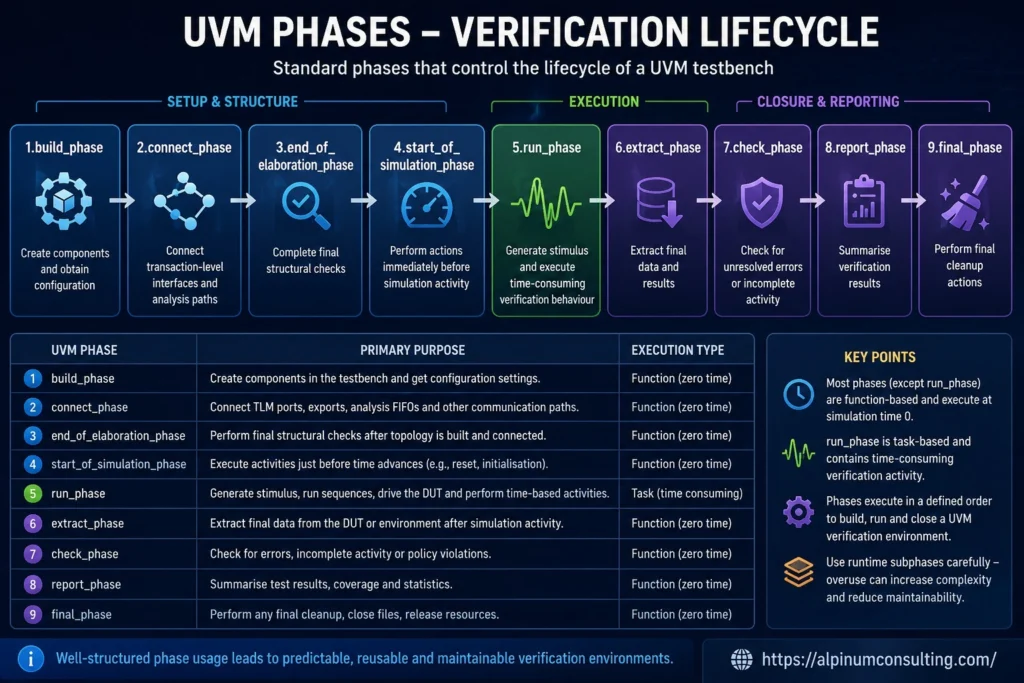
Figure 2: UVM phases provide a defined lifecycle for creating, connecting, executing, checking and closing a verification environment.
| UVM phase | Primary purpose |
| build_phase | Create components and obtain configuration |
| connect_phase | Connect transaction-level interfaces and analysis paths |
| end_of_elaboration_phase | Complete final structural checks |
| start_of_simulation_phase | Perform final actions before time-based activity begins |
| run_phase | Generate stimulus and execute time-consuming verification behaviour |
| extract_phase | Extract final data and results |
| check_phase | Check for unresolved errors or incomplete activity |
| report_phase | Summarise verification results |
| final_phase | Perform final cleanup actions |
Most structural phases are function-based and do not consume simulation time.
The run_phase is task-based and can include:
- Applying reset
- Starting sequences
- Driving transactions
- Waiting for responses
- Monitoring completion
- Handling timeouts
UVM also provides runtime subphases, but additional phase complexity should be used carefully. Excessive dependence on specialised runtime phases can make sequence execution and test completion harder to understand.
What Are UVM Objections?
Objections help determine when a task-based phase may finish.
A test raises an objection when required activity begins and drops it after that activity completes. The phase can end when no objections remain.
Poor objection handling can cause simulations to:
- Finish too early
- Continue indefinitely
- Depend on arbitrary delays
- Behave differently when sequences are reused
Objection control should therefore follow a clear project strategy rather than being distributed unpredictably across low-level components.
Constrained Random and Coverage-Driven Verification
Constrained random verification generates varied transactions while restricting them to legal or relevant combinations.
A transaction might randomise:
- Address
- Data
- Operation
- Burst size
- Delay
- Error conditions
Constraints prevent illegal values, define relationships between fields and focus generation on important scenarios.
Randomisation helps find combinations that engineers may not think to write manually. However, randomness is not proof of completeness.
It must be combined with:
- Verification planning
- Automated checking
- Functional coverage
- Assertions
- Coverage analysis
- Directed tests for remaining gaps
UVM does not replace directed testing. A UVM sequence can generate an exact deterministic scenario, and effective environments often combine directed smoke tests, constrained-random regressions, error injection and use-case testing.
Code Coverage Versus Functional Coverage
Code coverage measures which RTL structures were exercised. It may include:
- Statement coverage
- Branch coverage
- Expression coverage
- Toggle coverage
- Finite-state-machine coverage
Functional coverage measures whether planned behaviours and combinations occurred.
It should answer questions such as:
- Were all transaction types generated?
- Were all error responses observed?
- Were all privilege modes tested?
- Were important feature combinations exercised?
Neither metric is sufficient by itself.
High code coverage does not prove that requirements were checked. High functional coverage does not prove that the checker would detect an incorrect result.
Coverage must be interpreted alongside assertions, scoreboard results, requirement traceability and testbench quality.
Benefits of UVM
Reusable Verification Components
Agents, sequences, drivers and monitors can be reused across projects when designed with stable interfaces and controlled configuration.
Standard Architecture
Common component roles and phases make environments easier for engineering teams to understand.
Scalability
A testbench can grow from IP-level verification into a larger subsystem or SoC environment.
Separation of Responsibilities
Stimulus, driving, monitoring, prediction, checking and coverage are handled independently.
Coverage-Driven Verification
Coverage gaps can guide targeted stimulus and closure decisions.
Configuration and Extension
Tests can modify behaviour through configuration objects, sequences and factory overrides.
Regression Automation
UVM supports automated checking, reporting and large regression environments.
Limitations of UVM
UVM is powerful, but it does not solve every verification problem automatically.
Learning Curve
Engineers must understand SystemVerilog, object-oriented programming and UVM-specific concepts such as phases, factories, TLM and objections.
Complexity
Poorly designed environments can contain excessive abstraction, inheritance and configuration.
Debug Difficulty
Factory overrides and hidden configuration can make it difficult to determine which components are active.
Simulation Overhead
Randomisation, transaction processing and excessive reporting can increase simulation cost.
False Confidence
A large regression and high coverage numbers do not prove that requirements or checking are complete.
Not Necessary for Every Block
A very small and stable design may be verified more efficiently with a lightweight testbench or formal verification.
UVM at IP, Subsystem and SoC Level
At IP level, UVM may verify protocol compliance, registers, data paths, reset behaviour and error handling.
At subsystem level, it may coordinate several agents and check end-to-end behaviour across multiple interfaces.
At SoC level, UVM may be combined with:
- Embedded software
- Processor models
- Emulation
- FPGA prototyping
- C or C++ reference models
- Formal verification
- Hardware-software co-verification
UVM is also valuable in processor and RISC-V environments, where it may support instruction generation, memory models, peripheral interfaces and architectural checking. Alpinum’s RISC-V Verification Training covers practical CPU and SoC verification strategies.
UVM Versus Formal Verification
UVM simulation executes selected scenarios over time. Formal verification mathematically analyses whether specified properties hold across reachable states within the defined model.
| UVM simulation | Formal verification |
| Executes generated scenarios | Explores reachable states mathematically |
| Strong for realistic transaction flows | Strong for control logic and exhaustive properties |
| Supports long use cases and software interaction | Often requires focused or decomposed models |
| Uses scoreboards, coverage and assertions | Uses assumptions, assertions and proof results |
The approaches are complementary rather than competing.
UVM can handle realistic transaction flows while formal methods prove critical protocol, safety or security properties. Alpinum’s formal verification services support the integration of formal analysis with broader simulation workflows.
UVM and AI-Assisted Verification
AI tools may assist with:
- Specification analysis
- UVM code generation
- Sequence generation
- Assertion suggestions
- Coverage-gap analysis
- Regression triage
- Debug support
However, generated verification artefacts still require engineering review.
Teams must assess:
- Protocol correctness
- Requirement traceability
- Reset handling
- Checking independence
- Coverage relevance
- Simulator compatibility
- Maintainability
AI does not remove the need for verification architecture or engineering judgement. It should operate within controlled workflows such as those explored through Alpinum’s AI in Design Verification services.
How Should Engineers Learn UVM?
Engineers should first understand the verification-focused features of SystemVerilog, including simulation behaviour, interfaces, classes, constrained randomisation, assertions and functional coverage. They can then apply these capabilities through standard UVM components such as sequences, drivers, monitors, agents and scoreboards.
The most effective approach is to build a small self-checking SystemVerilog testbench first, separate stimulus, driving, monitoring and checking, and then rebuild the environment using UVM. Engineers deciding where to begin can follow our practical SystemVerilog and UVM learning path.
Engineers can then progress to introductory or advanced UVM training depending on their existing experience.
Alpinum’s UVM Introduction Training covers testbench structure, sequences, configuration, factories, scoreboards, TLM, register models and debug.
Experienced engineers can progress to Advanced UVM Training or the wider Design Verification for SV/UVM Training.
Conclusion
UVM is a standard methodology for building structured, reusable and coverage-driven SystemVerilog verification environments.
Its value comes from separating stimulus generation, interface driving, monitoring, prediction, checking, coverage and configuration into clearly defined components.
A well-designed UVM environment can help a verification team:
- Reuse verification IP
- Scale from block to SoC level
- Generate constrained-random stimulus
- Automate checking and reporting
- Measure meaningful functional coverage
- Improve regression and closure workflows
- Maintain a consistent team architecture
UVM does not replace verification planning, assertions, formal methods or engineering judgement. It provides the infrastructure through which these activities can be organised more effectively.
Engineers and semiconductor teams can explore Alpinum’s complete range of semiconductor verification training programmes, covering SystemVerilog, UVM, design verification, Formal Verification, RISC-V and related engineering workflows.
FAQs
UVM stands for Universal Verification Methodology.
No. UVM is a verification methodology and class library implemented using SystemVerilog.
A UVM testbench is a class-based environment containing sequences, sequencers, drivers, monitors, agents, scoreboards, coverage collectors, environments and tests.
A UVM agent packages components associated with a DUT interface. An active agent normally contains a sequencer, driver and monitor.
A virtual sequencer coordinates activity across several interface-level sequencers, particularly in subsystem and SoC environments.
UVM RAL is the Register Abstraction Layer used to model and access registers, fields, memories and address maps.
No. UVM simulation and formal verification address different verification needs and are usually most effective when used together.
Yes. It can be used for complex FPGA designs requiring reusable components, constrained-random stimulus and functional coverage.
UVM has a substantial learning curve because it combines SystemVerilog, object-oriented programming and verification methodology. Practical testbench development and debugging are the most effective ways to learn it.

Written by : Mike Bartley
Mike started in software testing in 1988 after completing a PhD in Math, moving to semiconductor Design Verification (DV) in 1994, verifying designs (on Silicon and FPGA) going into commercial and safety-related sectors such as mobile phones, automotive, comms, cloud/data servers, and Artificial Intelligence. Mike built and managed state-of-the-art DV teams inside several companies, specialising in CPU verification.
Mike founded and grew a DV services company to 450+ engineers globally, successfully delivering services and solutions to over 50+ clients.
Mike started Alpinum in April 2016 to deliver a range of start-of-the art industry solutions:
Alpinum AI provides tools and automations using Artificial Intelligence to help companies reduce development costs (by up to 90%!) Alpinum Services provides RTL to GDS VLSI services from nearshore and offshore centres in Vietnam, India, Egypt, Eastern Europe, Mexico and Costa Rica. Alpinum Consulting also provides strategic board level consultancy services, helping companies to grow. Alpinum training department provides self-paced, fully online training in System Verilog, UVM Introduction and Advanced, Formal Verification, DV methodologies for SV, UVM, VHDL and OSVVM and CPU/RISC-V. Alpinum Events organises a number of free-to-attend industry events
You can contact Mike (mike@alpinumconsulting.com or +44 7796 307958) or book a meeting with Mike using Calendly (https://calendly.com/mike-alpinum-consulting).
Stay Informed and Stay Ahead
Latest Articles, Guides and News
Explore related insights from Alpinum that dive deeper into design verification challenges, practical solutions, and expert perspectives from across the global engineering landscape.