
Key Learning Points
| Key learning point | Detailed section | External reference |
| UCIe 3.0 doubles the maximum data rate to 64 GT/s and expands manageability. | Why UCIe 3.0 Changes the Verification Problem | [1]-[3] |
| Runtime recalibration must be verified under active traffic, power-state changes and recovery conditions. | Runtime Recalibration During Active Traffic | [2], [3], [7] |
| Firmware, priority sideband packets and emergency controls expand the hardware/software verification boundary. | Priority Sideband, Firmware Download and Manageability | [1]-[3] |
| Compliance is necessary but does not prove multi-vendor interoperability under realistic workloads. | Multi-Vendor Interoperability: Compliance Is Necessary but Not Sufficient | [4]-[6] |
| Manufacturing-test evidence must carry forward from Known-Good Die through package-level validation and failure isolation. | From Known-Good Die to package-level test | Alpinum/OCP SiP work |
Executive Summary
UCIe 3.0 is not simply a faster version of a die-to-die interface. Released by the UCIe Consortium in August 2025, it adds 48 GT/s and 64 GT/s operation for UCIe-S and UCIe-A, extends sideband reach to 100 mm, standardises early firmware download through the Management Transport Protocol, introduces priority sideband packets, supports continuous-transmission mappings in Raw Mode, and adds runtime recalibration and fast system-wide throttle or shutdown mechanisms. The specification remains backward compatible with earlier UCIe revisions. [1]-[3]
Those additions widen the verification problem. A team can no longer prove readiness by showing that link training completes and packets move correctly in a nominal configuration. It must demonstrate that high-speed links remain reliable across process, voltage and temperature variation; recalibration does not corrupt active traffic; firmware and management flows recover safely; priority controls meet latency expectations; and independently developed dies interoperate as a complete System-in-Package.
The practical consequence is a shift from interface verification towards evidence-based multi-die sign-off. RTL simulation remains essential for detailed debug and coverage. Formal methods are valuable for state machines, arbitration, liveness and safety properties. Emulation is needed for firmware, operating-system and long-duration workload testing. FPGA prototypes can accelerate hardware/software integration. Post-silicon validation must correlate functional expectations with electrical, package and compliance measurements.
This guide focuses on that verification problem. Readers needing that foundation can first review system-level verification in the chiplet era and why chiplet verification and test must scale.
Why UCIe 3.0 Changes the Verification Problem
UCIe defines a layered interconnect for chiplets inside a package. Its scope includes the physical layer, die-to-die adapter, configuration and link management, protocol mappings and compliance mechanisms. The open ecosystem objective is important: dies may come from different vendors, use different process technologies and be assembled in different package structures. [1], [5]
UCIe 2.0 already made manageability, debug, test and 3D packaging more prominent. UCIe 3.0 adds higher rates and operational features that change behaviour after initialisation. The verification target is therefore dynamic. A link may recalibrate while the system is running. Firmware may participate in early configuration. Sideband traffic may carry time-sensitive or emergency information. Power states may affect both mainband and sideband behaviour. Raw Mode may carry continuous-transmission streams that do not resemble ordinary packet traffic.
These interactions create a larger state space and more cross-domain failure modes. A local PHY result can depend on firmware policy. A power event can affect protocol ordering. A recovery action can preserve the link while silently violating an end-to-end software assumption. Verification must connect requirements across layers instead of proving each layer in isolation.
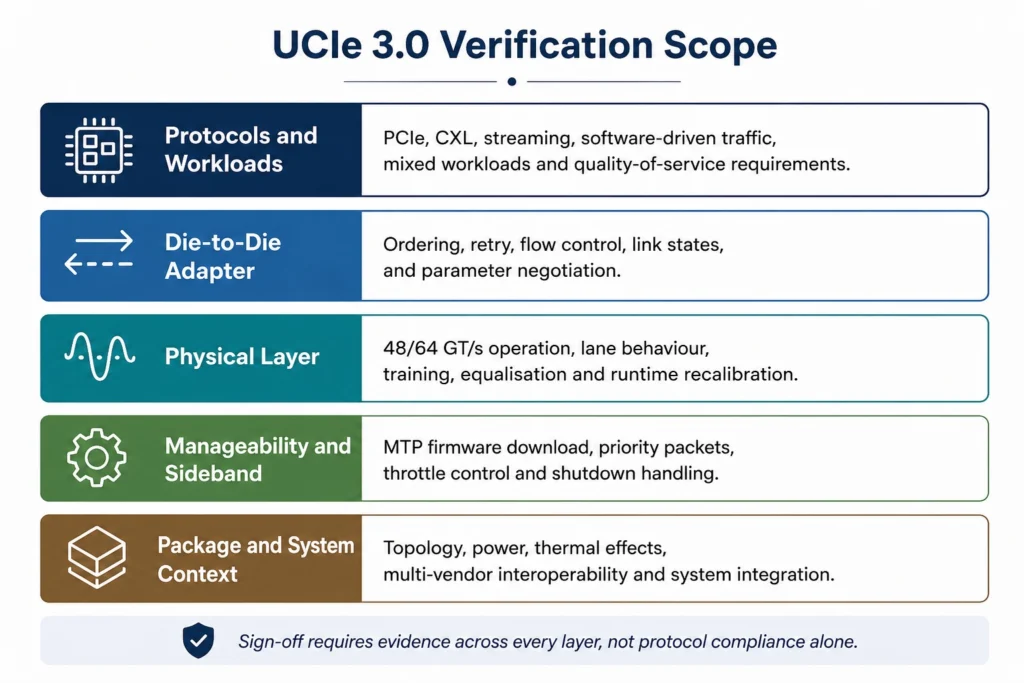
Figure 1: UCIe 3.0 verification spans protocol workloads, the die-to-die adapter, physical-layer behaviour, manageability and the package-level system context.
UCIe 2.0 Versus UCIe 3.0: Verification Impact
| Area | UCIe 2.0 | UCIe 3.0 | Verification impact |
| Maximum planar data rate | 32 GT/s | 48 GT/s and 64 GT/s | More aggressive timing, jitter, skew and long-duration stress scenarios |
| Runtime link behaviour | Initial training and existing reliability flows | Runtime TX recalibration and L2 optimisation | Verify recalibration triggers, active traffic, power saving and restoration |
| Sideband reach | Shorter established topologies | Up to 100 mm | Exercise topology, routing, latency and error cases across longer paths |
| Firmware management | Manageability baseline | Early firmware download using MTP | Add boot sequencing, versioning, timeout and recovery scenarios |
| Priority control | Baseline sideband messaging | Priority sideband packets | Verify arbitration, ordering and deterministic event latency |
| Emergency response | Existing management controls | Fast throttle and emergency shutdown through open-drain signalling | Prove urgent notification, safe transition and recovery |
| Raw Mode | Raw transport support | Continuous-transmission protocol mappings | Verify uninterrupted streams, entry/exit and mixed operating modes |
| Compatibility | Backward compatible with UCIe 1.x | Backward compatible with all previous revisions | Build mixed-version capability negotiation and downgrade tests |
Table 1: UCIe 3.0 feature changes and the verification work they introduce. Specification facts are based on official UCIe Consortium summaries [1]-[3].
Build the Verification Strategy Around Requirements, Not Tools
A robust UCIe plan begins with a requirements model. Every supported speed, width, package option, protocol mapping, power state, manageability feature, firmware revision and interoperability configuration should be explicit. Optional specification features must be marked as implemented, unsupported or reserved. This prevents a common sign-off failure: collecting coverage against the testbench configuration rather than the product configuration.
The testbench should then separate reusable protocol components from product-specific policy. A typical environment contains UCIe verification IP or equivalent agents, monitors at the RDI and FDI boundaries where available, end-to-end scoreboards, firmware or management agents, fault-injection controls, power-aware models and a coverage model tied to requirements. The same intent should be reusable from IP level to die, subsystem and SiP integration.
Teams developing this infrastructure can use SystemVerilog and UVM verification training to strengthen reusable environment design, scoreboarding, assertions and coverage planning.
Recommended Verification Architecture
- Requirements and configuration model: defines supported UCIe revisions, rates, widths, protocols, package types and optional features.
- Layered stimulus: creates physical, adapter, protocol, sideband, management and firmware scenarios without hard-wiring one implementation.
- Independent checking: combines protocol checkers, end-to-end scoreboards and golden behavioural models.
- Cross-layer observability: correlates link states, packets, firmware operations, power events and errors using a common timeline.
- Requirements-driven coverage: measures implemented product scenarios, including cross coverage for combinations that create risk.
- Portable sign-off evidence: preserves test, assertion, coverage and failure data for reuse in emulation, prototyping and post-silicon planning.
Define the Chiplet Verification Delivery Contract
Before integration begins, each chiplet provider and the system integrator should agree what verification evidence accompanies the delivered die. The package should include the supported UCIe revision, rates and widths; implemented and optional capabilities; firmware dependencies; compliance status; requirements traceability; coverage exclusions; known errors; reference-model assumptions; debug access; recovery behaviour and post-silicon correlation requirements.
Without this delivery contract, individually verified chiplets can arrive with incompatible assumptions about timeouts, optional features, power states, firmware ownership or error recovery. Those gaps frequently become system-level integration defects rather than local interface failures.
Verifying 48 GT/s and 64 GT/s Die-to-Die Links
The physical-layer headline in UCIe 3.0 is the increase from 32 GT/s to 48 GT/s and 64 GT/s for both UCIe-S and UCIe-A. [1]-[3] A digital simulation cannot replace package and electrical analysis, but functional verification still carries important responsibilities. It must prove correct speed negotiation, training, lane mapping, repair and reversal behaviour, state transitions, error reporting and recovery under the product’s supported configurations.
The risk increases when high-speed operation is combined with traffic and management activity. Verification should not isolate link training from workload behaviour. Stress scenarios should include bidirectional saturation, bursty traffic, protocol mixing where supported, credit pressure, retry, power-state entry, recalibration, firmware commands and injected lane or packet errors. The most valuable tests often cross boundaries: a retry during a management event, a power transition near recalibration, or a degraded link carrying latency-sensitive traffic.
What Pre-Silicon Verification Should Prove
- Each legal speed, width and package configuration negotiates correctly, while unsupported combinations fail safely.
- Link training and recovery terminate within defined bounds, with no illegal or deadlocked states.
- Data integrity and ordering are preserved through retry, replay, lane degradation and retraining.
- Error status is visible to the correct management or firmware entity and cannot be silently lost.
- Performance counters and latency measurements remain meaningful under sustained traffic and feature interactions.
- Electrical assumptions used by behavioural models are traceable to package, PHY and compliance plans.
Post-silicon teams should extend this evidence with eye, jitter, bit-error-rate, channel and package measurements. Cadence describes UCIe compliance as spanning electrical, mechanical, adapter, protocol and PHY considerations, including the connection of a golden die to the device under test. [6] The verification plan should therefore define the correlation points before tape-out rather than treating compliance as a separate laboratory exercise.
Runtime Recalibration During Active Traffic
Runtime TX recalibration is one of the most important UCIe 3.0 changes because it turns calibration from an initialisation event into an operational behaviour. The Consortium describes the mechanism as a way to tune the link efficiently during operation by reusing initialisation states, while L2 optimisation supports lower idle power. [1]-[3]
The verification objective is not merely to observe a recalibration request. The environment must prove that the trigger is legal, both link partners agree on the transition, traffic is handled according to the specification and implementation policy, completion is reported correctly, and the link returns to an expected state. Error paths matter equally: a timeout, rejected request, interrupted calibration or firmware conflict must not leave the system partially operational.
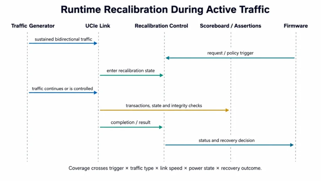
Figure 2: Example verification sequence for runtime recalibration under active traffic.
Coverage That Matters
| Coverage dimension | Examples |
| Trigger | Periodic, firmware-requested, condition-driven, simultaneous request |
| Traffic state | Idle, low-rate, saturated, bidirectional, mixed protocols |
| Link configuration | 48 GT/s, 64 GT/s, supported widths, repaired or degraded lane state |
| Power context | Active, transition to L2, return from low power, thermal throttle |
| Outcome | Success, timeout, rejection, interruption, retry, reset recovery |
| Cross coverage | Trigger x traffic x speed x power state x outcome |
Assertions should check legal state transitions, bounded completion, stable ordering guarantees, credit integrity and eventual recovery. Formal verification can be especially effective on the recalibration controller because rare interleavings are difficult to exhaust with simulation.
Priority Sideband, Firmware Download and Manageability
UCIe 3.0 extends system manageability through early firmware download using the Management Transport Protocol, priority sideband packets, longer sideband reach and low-latency open-drain events. It also adds fast throttle and emergency shutdown notification. [1]-[3] These features are operationally useful because a complex SiP may contain chiplets that need configuration, health reporting or urgent control before the full mainband path is available.
They also introduce a verification boundary between hardware, firmware and system policy. The design must route management traffic correctly across the chosen topology, honour priority without starving ordinary management operations, reject malformed or unsupported transactions, and maintain security and access controls. Firmware download needs version and image handling, ordering, timeout, partial-transfer and recovery scenarios. A successful transfer is not enough if the receiving chiplet starts from an inconsistent configuration.
Priority Sideband Verification Objectives
- Prove deterministic handling of supported priority classes and define the latency measurement point.
- Exercise simultaneous normal and priority traffic, including repeated urgent events.
- Check ordering where ordering is required and safe independence where it is not.
- Inject CRC, timeout, route and destination errors and verify that the error is reported to the correct owner.
- Validate longer-reach and star-topology assumptions in the model and the post-silicon plan.
- Confirm that power-down and wake-up behaviour does not lose a pending critical event.
Firmware Download and Boot Scenarios
| Scenario | Required evidence |
| Normal boot | Supported image, expected discovery and configuration sequence |
| Version mismatch | Older or newer image, unsupported capability and explicit rejection |
| Interrupted transfer | Reset, power event, link error or management timeout during download |
| Multi-chiplet dependency | One chiplet waits for or configures another; ordering and timeout are checked |
| Recovery | Retry, rollback, safe state and diagnostic visibility |
| Security boundary | Authorisation, protected debug/management access and failure reporting |
MIPI Debug Over UCIe provides another important system-level use case. It supports debug control and trace over UCIe mainband or sideband links, coexistence with functional traffic and concurrent debug of multiple chiplets. [4] Verification teams should reserve bandwidth, ordering and access-control scenarios for debug traffic rather than assuming it is invisible to the functional system.
Power Throttling, Emergency Shutdown, Raw Mode and Recovery
Fast throttle and emergency shutdown features are intended to distribute urgent system-wide notifications. [1], [2] A useful verification plan treats these as end-to-end safety mechanisms rather than isolated pins or messages. The event must be generated under the correct condition, reach every required destination, cause an allowed transition, preserve diagnostic evidence and recover only when the system policy permits.
The difficult cases are races. A throttle can arrive during firmware download, recalibration, link training or a low-power transition. An emergency event can affect several chiplets that have different local clocks or power states. The checker must distinguish the permitted loss of ordinary progress from impermissible data corruption or inconsistent state.
UCIe 3.0 also supports continuous-transmission protocol mappings through Raw Mode, including SoC-to-DSP or ADC/DAC-oriented use cases. [1]-[3] Verification should cover mode entry, sustained streaming, clocking assumptions, backpressure or flow policy where applicable, error visibility and exit back to normal operation. Continuous transmission deserves long-duration testing because short directed tests rarely expose drift, periodic interference or buffer-management defects.
UCIe also operates within wider open-chiplet integration frameworks. The Open Compute Project’s Universal D2D Transaction and Link-Layer work with UCIe supports UCIe as an underlying die-to-die transport while keeping higher-level transaction services more independent of the selected physical interface. Verification must therefore address not only the UCIe link but also profile selection, protocol mapping, Raw streaming behaviour and the contract between independently developed transaction and physical layers.
Multi-Vendor Interoperability: Compliance Is Necessary but Not Sufficient
The value of UCIe depends on interoperable chiplets. The specification provides common physical, adapter, protocol and compliance foundations. However, two individually compliant implementations can still expose integration defects through capability interpretation, firmware policy, optional-feature support, timeout values, recovery behaviour or workload assumptions. IEEE’s overview of UCIe identifies compliance and interoperability as central to an open chiplet ecosystem. [5]
Interoperability testing should therefore begin before physical devices are available. Simulation can pair a device under test with independent verification IP, a golden model or another vendor model. Cadence and Intel describe a shift-left approach to UCIe interoperability through simulation and golden-die correlation, while Siemens presents layered, topology-aware UCIe verification architectures for manageability and 3.0 features. [6], [7]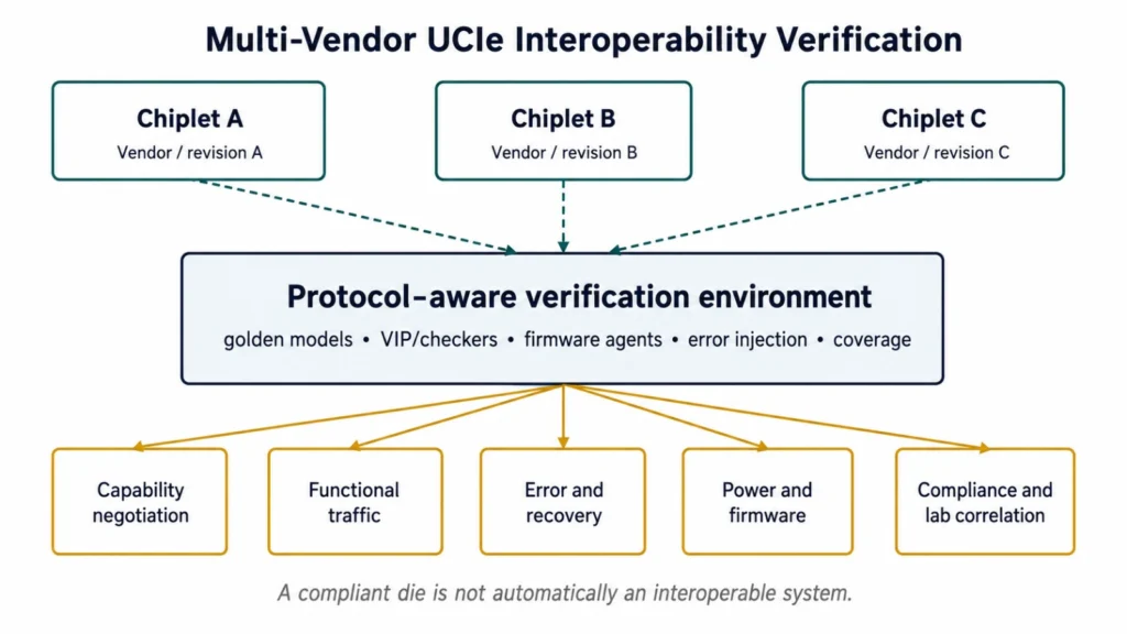
Figure 3: Multi-vendor interoperability verification should combine independent models, firmware agents, fault injection, coverage and compliance correlation.
Interoperability Test Dimensions
- Vendor, IP version, RTL revision and firmware-image combinations.
- Capability discovery, supported-feature negotiation and mixed UCIe revision operation.
- UCIe-S, UCIe-A and any supported package/topology constraints.
- Normal traffic, congestion, retry, lane degradation, recalibration and low-power states.
- Priority management, debug coexistence, firmware transfer and emergency events.
- Graceful rejection of unsupported configurations and repeatable recovery after failure.
| Engineering rule: Do not compare one implementation directly with another and call the result correct. Compare both against specification-derived requirements and an independent reference model. |
UCIe 3.0 Verification Responsibility Matrix
| Verification objective | RTL simulation | Formal | Emulation | FPGA prototype | Post-silicon |
| Link training and negotiation | Primary | Strong for control | Useful | Useful | Required |
| 48/64 GT/s protocol behaviour | Primary | Targeted | Strong | Useful | Required |
| Runtime recalibration | Primary | Strong for controller | Strong | Limited | Required |
| Priority sideband and MTP | Primary | Strong | Strong | Useful | Required |
| Firmware boot and download | Limited | Targeted | Primary | Strong | Required |
| Power and emergency recovery | Primary | Strong | Strong | Useful | Required |
| Raw continuous transmission | Targeted | Limited | Strong | Strong | Required |
| Multi-vendor interoperability | Strong with models | Limited | Strong | Strong | Required |
| Long-duration workloads | Weak | Not applicable | Primary | Primary | Required |
| Electrical and package compliance | Model correlation | Not applicable | Limited | Limited | Primary |
Table 2: Recommended allocation of UCIe verification evidence. “Primary” identifies the environment best suited to closing the objective; no single environment replaces the others.
This division matters because simulation gives detailed visibility but cannot efficiently run every software workload. Formal methods provide exhaustive control-logic analysis but do not prove analogue channel behaviour. Emulation and prototyping extend time and software scale, while post-silicon validation provides the real electrical and package evidence. For teams that need pre-silicon hardware/software integration, Alpinum’s FPGA design and verification services provide a relevant internal route.
Common UCIe Verification Failures and How to Prevent Them
| Failure | Programme consequence | Prevention |
| Verifying only nominal link traffic | Corner cases escape when power, errors or manageability overlap | Cross traffic, power, error, recalibration and firmware coverage |
| Treating firmware as a later activity | Boot and recovery defects appear in emulation or silicon | Executable firmware models and early emulation milestones |
| Using coverage percentages without requirement traceability | High coverage creates false confidence | Requirement-to-test, assertion and coverpoint mapping |
| Assuming compliance proves interoperability | Mixed-vendor integration fails despite local compliance | Independent models, mixed revisions and golden-die correlation |
| Ignoring long-duration behaviour | Drift, periodic errors and resource leaks remain hidden | Emulation, prototype and soak-test targets |
| Planning post-silicon after tape-out | Poor observability and slow root-cause analysis | Define counters, trace, debug access and lab correlation early |
| Overloading one testbench with implementation assumptions | Reuse fails at die or vendor boundaries | Layered agents, policy separation and configurable topology |
A further risk is applying AI to UCIe verification without traceability. AI can assist failure clustering, log summarisation, coverage-gap analysis and regression prioritisation, but sign-off decisions still require explainable evidence and engineering review.
From Known-Good Die to Package-Level Test
Functional verification and protocol compliance do not complete the UCIe test strategy. A multi-die programme must also determine how test evidence moves from the individual chiplet to the assembled package.
Each chiplet supplier should define the test coverage already completed, supported test and debug access, known limitations, repair status and the conditions used to classify a die as suitable for integration. The system integrator must then verify die-to-die connectivity, package-level interconnects, power delivery, thermal behaviour and failure isolation after assembly.
Hierarchical test planning is important because repeating every die-level test at package level may be impractical, while relying entirely on supplier evidence can leave integration defects undetected. The sign-off plan should therefore identify which results can be reused, which tests must be repeated and which package-level scenarios require new structural, functional or software-driven testing.
Correlation must also be planned between pre-silicon fault models, embedded diagnostic mechanisms, production-test results and laboratory debug. When a multi-die package fails, the team needs enough observability to determine whether the cause lies in a chiplet, the UCIe interface, the package, firmware or the wider system configuration.
Alpinum’s approach to multi-die verification is also informed by work connected with the Open Compute Project. Mike Bartley and other industry experts have contributed to OCP white-paper activity covering System-in-Package verification and testing. This work examines how verification and test evidence must extend from independently developed chiplets to the integrated package, including system-level failure modes, reusable verification evidence, Known-Good Die considerations and the practical roadmap required for scalable multi-vendor integration.
Practical UCIe 3.0 Sign-Off Checklist
A passing regression is not a tape-out decision. Sign-off should demonstrate that the product configuration meets its requirements and that unresolved risk is visible, owned and accepted. The following checklist can be adapted into a programme review.
| Review area | Exit criterion | Evidence |
| Requirements and configuration | Supported revisions, rates, widths, protocols, package options and optional features are baselined. | Approved requirements and configuration matrix |
| Protocol and link control | Training, negotiation, ordering, credits, retry, errors and recovery are closed. | Regression, assertions and traceability report |
| 64 GT/s stress | Maximum-rate configurations are tested with realistic traffic and feature interactions. | Stress results and lab-correlation plan |
| Runtime recalibration | Triggers, active traffic, completion, timeout and recovery are covered. | Coverage crosses and formal/simulation evidence |
| Manageability and firmware | MTP, discovery, versioning, priority messaging and boot recovery are validated. | Firmware/emulation report |
| Power and emergency control | L2, throttle, shutdown and restart sequences are proven safe. | Power-aware tests and properties |
| Raw Mode | Entry, continuous transmission, errors and exit are validated where implemented. | Streaming and long-duration results |
| Interoperability | Independent models and representative vendor/revision combinations pass. | Interop matrix and compliance correlation |
| Chiplet delivery contract | Supplier evidence, assumptions, exclusions, firmware dependencies and debug access are agreed. | Approved chiplet delivery package |
| Package-level test | Known-Good Die evidence, package interconnect testing and failure isolation are planned. | Hierarchical test and correlation plan |
| Coverage closure | Exclusions are reviewed; cross coverage reflects product risk. | Signed coverage report |
| Post-silicon readiness | Debug, telemetry, compliance, BER and package tests are planned. | Approved validation plan and ownership |
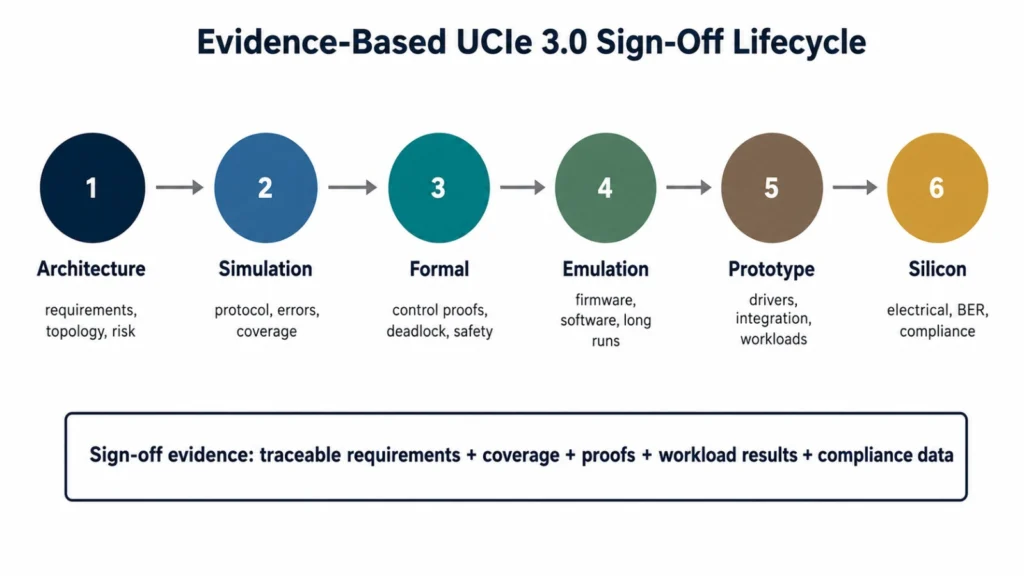
Figure 4: UCIe 3.0 sign-off should accumulate traceable evidence across architecture, simulation, formal, emulation, prototyping and silicon.
Conclusion: Treat UCIe 3.0 as a System Verification Problem
UCIe 3.0 gives multi-die architects more bandwidth, power control, manageability and design flexibility. Those benefits also make verification more cross-layer and more operational. Link correctness must survive recalibration, firmware activity, power transitions, urgent control events, debug traffic and mixed-vendor integration. A local pass at one interface is not enough.
The strongest programmes define product configurations early, agree a clear chiplet delivery contract, build reusable but independent checking, connect coverage to requirements, use formal analysis on control-heavy corner cases, execute firmware and long workloads in emulation, carry test evidence from Known-Good Die into package-level validation, and preserve correlation into prototype and post-silicon testing. This approach does not eliminate risk, but it makes risk measurable before tape-out.
For teams planning a new UCIe or multi-die programme, contact Alpinum Consulting to discuss verification architecture, coverage closure, formal verification, emulation strategy, package-level test planning or independent sign-off review.
References
[1] UCIe Consortium, “UCIe 3.0 specification highlights,” UCIe Consortium. [Online]. Available: https://www.uciexpress.org/specifications
[2] UCIe Consortium, “UCIe Consortium introduces 3.0 specification with 64 GT/s performance and enhanced manageability,” UCIe Consortium, Aug. 5, 2025. [Online]. Available: https://www.uciexpress.org/_files/ugd/8dc731_ae67289d0ec646cdba5c1aee245538b3.pdf
[3] D. Das Sharma, “Introducing the UCIe 3.0 specification: Continued innovations in the open chiplet ecosystem,” webinar presentation, UCIe Consortium, Sep. 18, 2025. [Online]. Available:https://www.uciexpress.org/_files/ugd/0c1418_b4744fe368c94e3e9c7eaa13ead632bf.pdf
[4] MIPI Alliance, “MIPI Debug over UCIe,” specification overview, MIPI Alliance. [Online]. Available: https://www.mipi.org/specifications/debug-over-ucie
[5] P. Onufryk and S. Choudhary, “UCIe: Standard for an open chiplet ecosystem,” IEEE Micro, vol. 45, no. 1, pp. 16–25, 2025.[Online]. Available:https://www.computer.org/csdl/magazine/mi/2025/01/10669138/201rUGJnOog
[6] Cadence Design Systems, “Intel and Cadence collaboration on UCIe,” white paper, 2024. [Online]. Available: https://www.cadence.com/en_US/home/resources/white-papers/intel-and-cadence-collaboration-on-ucie-wp.html
[7] Siemens EDA, “From manageability to 3.0: Unlocking the future with UCIe verification,” Sep. 26, 2025. [Online]. Available:https://blogs.sw.siemens.com/verificationhorizons/2025/09/26/from-manageability-to-3-0-unlocking-the-future-with-ucie-verification/
[8] Synopsys, “UCIe 3.0: Next-generation chiplet connectivity and IP solutions,” Aug. 5, 2025. [Online]. Available: https://www.synopsys.com/blogs/chip-design/ucie-3-0-chiplet-ip-solutions.html
FAQs
UCIe 3.0 verification is the process of proving that a chiplet or multi-die system implements the required UCIe physical, adapter, protocol and manageability behaviour. It includes high-speed link control, runtime recalibration, firmware and sideband flows, power management, interoperability and sign-off evidence across pre-silicon and post-silicon environments.
UCIe 3.0 added 48 GT/s and 64 GT/s planar data rates, runtime recalibration, L2 power optimisation, sideband reach up to 100 mm, continuous-transmission mappings in Raw Mode, early firmware download using MTP, priority sideband packets, open-drain event support and fast throttle or emergency shutdown. It remains backward compatible with previous UCIe revisions. [1]-[3]
It can occur while the link is operational, so verification must consider traffic, link state, power state, firmware policy and error recovery together. A correct trigger is insufficient if packets are lost, ordering changes unexpectedly, or the link fails to return to a defined state.
No. Compliance establishes conformance to defined requirements and test procedures, but integration can still fail through optional features, capability interpretation, firmware versions, timeout policy or recovery behaviour. Interoperability requires representative partner models or devices and system-level workloads.
UVM can provide reusable agents, sequences, scoreboards, coverage and configuration for UCIe environments. It is a methodology rather than the ranking target of this page. The verification architecture should remain requirement-driven and should separate protocol behaviour from product-specific policy.
Formal methods are useful for link and management state machines, arbitration, liveness, credit conservation, deadlock analysis, bounded response and safe power or emergency transitions. They complement rather than replace simulation and electrical validation.
Emulation can run real firmware, boot sequences, operating systems and long-duration traffic at a scale that RTL simulation cannot reach efficiently. It is particularly useful for firmware download, multi-chiplet initialisation, recalibration under workloads and repeated recovery scenarios.
It is the agreed evidence package supplied with a chiplet, including supported UCIe capabilities, requirements traceability, compliance status, coverage exclusions, firmware dependencies, reference-model assumptions, known errors, debug access and recovery behaviour. The contract prevents incompatible assumptions from appearing only during SiP integration.
The programme should define which Known-Good Die and die-level results can be reused, which tests must be repeated after assembly and which package-level structural, functional, software-driven and interconnect tests are new. Failure isolation and pre-silicon-to-lab correlation must be planned before tape-out.
Define the pre-silicon-to-lab correlation points before tape-out. These normally include link states, error counters, trace, BER and electrical measurements, compliance procedures, package and thermal stress, interoperability configurations and repeatable reproduction of pre-silicon scenarios.
AI can help classify failures, summarise logs, identify coverage gaps and prioritise regressions. It should not replace requirement traceability, independent checking or human sign-off. Results need explainability and review boundaries.
It should include a baselined configuration, protocol and link evidence, maximum-rate stress, recalibration closure, firmware and manageability results, power and emergency recovery, Raw Mode evidence where relevant, interoperability results, an agreed chiplet delivery contract, package-level test planning, coverage exclusions and an approved post-silicon validation plan.

Written by : Mike Bartley
Mike started in software testing in 1988 after completing a PhD in Math, moving to semiconductor Design Verification (DV) in 1994, verifying designs (on Silicon and FPGA) going into commercial and safety-related sectors such as mobile phones, automotive, comms, cloud/data servers, and Artificial Intelligence. Mike built and managed state-of-the-art DV teams inside several companies, specialising in CPU verification.
Mike founded and grew a DV services company to 450+ engineers globally, successfully delivering services and solutions to over 50+ clients.
Mike started Alpinum in April 2016 to deliver a range of start-of-the art industry solutions:
Alpinum AI provides tools and automations using Artificial Intelligence to help companies reduce development costs (by up to 90%!) Alpinum Services provides RTL to GDS VLSI services from nearshore and offshore centres in Vietnam, India, Egypt, Eastern Europe, Mexico and Costa Rica. Alpinum Consulting also provides strategic board level consultancy services, helping companies to grow. Alpinum training department provides self-paced, fully online training in System Verilog, UVM Introduction and Advanced, Formal Verification, DV methodologies for SV, UVM, VHDL and OSVVM and CPU/RISC-V. Alpinum Events organises a number of free-to-attend industry events
You can contact Mike (mike@alpinumconsulting.com or +44 7796 307958) or book a meeting with Mike using Calendly (https://calendly.com/mike-alpinum-consulting).
Stay Informed and Stay Ahead
Latest Articles, Guides and News
Explore related insights from Alpinum that dive deeper into design verification challenges, practical solutions, and expert perspectives from across the global engineering landscape.