
An automotive SoC functional safety verification flow starts with allocated safety requirements, not with a collection of fault-injection tests. Engineers identify which hardware and software behaviours must be demonstrated, map each requirement to safety mechanisms and interfaces, and build a fault model consistent with the safety analysis. Simulation, formal verification and controlled fault injection then establish evidence for fault activation, detection, reporting and the specified response. The results are traced back to requirements and used to examine assumptions in the failure modes, effects and diagnostic analysis (FMEDA). This is an SoC engineering verification workflow within a wider ISO 26262 safety lifecycle; successful regressions or fault campaigns alone do not establish vehicle-level functional safety or certification.
What Is a Functional Safety Verification Flow?
A functional safety verification flow is a requirements-led programme for checking whether safety-related electronic hardware behaves as specified both during intended operation and when relevant faults occur. Its critical distinction is the question being answered. Functional verification asks whether a memory returns the right data during normal operation. Functional safety verification also asks what happens when protected data is corrupted: is the condition detected, is the required diagnostic generated, and does the wider system take the specified action?
Four levels of evidence must remain separate:
- Functional behaviour: the SoC performs its intended transactions and control sequences.
- Safety-mechanism behaviour: defined faults produce the expected detection, correction, reporting or containment response.
- Safety analysis: evidence informs assumptions about failure modes, diagnostic coverage and hardware architectural metrics.
- System safety argument: allocated requirements, hardware and software evidence, integration, validation and applicable confirmation measures are evaluated together.
The flow below is an illustrative engineering implementation, not a complete or universally mandated sequence from ISO 26262. ISO 26262-11:2018 provides informative semiconductor guidance; Parts 3, 4, 5, 6, 8 and 9 cover distinct lifecycle responsibilities [1–7].
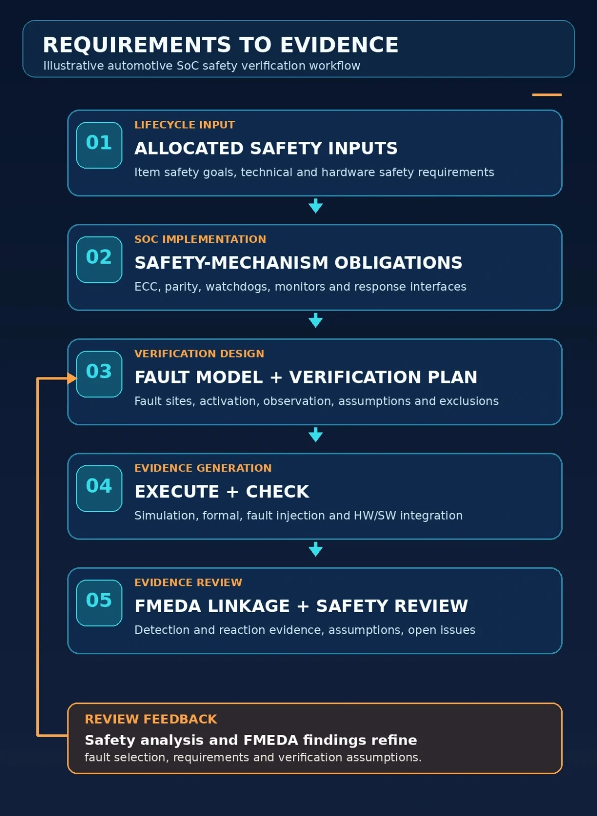
Figure 1: Requirements-to-evidence flow for automotive SoC functional safety verification. Allocated requirements inform safety-mechanism obligations and the verification plan. Simulation, formal analysis and fault injection produce detection-and-response evidence; FMEDA and safety review can feed back into fault selection and verification assumptions. The diagram is an illustrative engineering workflow, not the complete ISO 26262 lifecycle.
Step 1: Start with the Item, Safety Goals and Applicable Requirements
The verification team must know the origin, allocation and scope of each safety obligation. At item level, an item definition and hazard analysis and risk assessment (HARA) inform safety goals and the functional safety concept under ISO 26262-3. System-level work develops the technical safety concept and technical safety requirements under Part 4. Hardware safety requirements and the corresponding hardware architecture are developed under Part 5; software obligations are addressed through the appropriate system and software processes, including Part 6 [1–4].
An SoC verification team should therefore request a controlled set of allocated requirements, interfaces and assumptions rather than independently assign an Automotive Safety Integrity Level (ASIL) or infer a vehicle-level safe state. Those upstream decisions depend on item context and system-level safety engineering.
For example, a system requirement may call for a safety-relevant compute function to detect a specified class of internal memory corruption and initiate a defined diagnostic response. The semiconductor allocation might require an ECC decoder to report uncorrectable errors to a safety manager. The SoC team’s verification obligation is to demonstrate that signal chain and the allocated behaviour: not to claim that the entire vehicle hazard has been mitigated.
Give each requirement an identifier, owner, version, applicable operating modes, observable acceptance criteria and links to the relevant implementation. If a deadline appears in the requirement, record its origin and measurement points; do not invent one from the testbench clock. Alpinum’s broader guide to verification planning and coverage closure discusses the general traceability discipline that this safety-specific plan builds upon.
Step 2: Identify Safety Mechanisms and Their Verification Obligations
A safety architecture combines mechanisms that prevent, detect, tolerate, correct or control faults. Their obligations differ:
| Mechanism | Example behaviour to verify | Boundary to check |
| ECC-protected memory | Correct an in-scope single-bit error or signal a defined detected, uncorrectable pattern | Decoder status, data use, reporting and escalation |
| Parity or CRC check | Identify an applicable corrupted transfer | Error propagation to the receiving block and handler |
| Lockstep comparator | Report divergence under specified comparison conditions | Comparator, diagnostic route and response policy |
| Watchdog | Detect a missed service or timing violation | Timeout configuration, interrupt/reset and software integration |
| Clock/reset monitor | Report or handle an out-of-range or unexpected condition | Mode changes, reset sequencing and fault visibility |
| Safety manager | Aggregate, classify and route diagnostic events | Priorities, masks, escalation, acknowledgement and reset behaviour |
Do not collapse detection, reporting, handling and system reaction into a single pass condition. A parity flag may be correct while the event is masked in an interrupt controller. An ECC event may reach the safety manager but never trigger the allocated software response. The relevant requirements determine whether operation should continue, transition to a degraded mode, reset a subsystem or take another specified action; there is no universal response for every fault [8].
The plan should include both normal-mode checks and cross-cutting conditions such as reset, power transitions, clock gating, start-up tests, concurrent error sources and any required diagnostic self-tests. Check for common-cause or dependent-failure assumptions when a safety mechanism and the protected function share resources [6].
Step 3: Build a Fault Model and Fault-Injection Plan
The fault campaign starts from the failure modes and assumptions in the safety analysis. Candidate classes may include single- or multi-bit storage corruption, relevant transient or permanent logic faults, stuck-at conditions, incorrect control transitions and specified clock/reset disturbances. A campaign should not inject every imaginable fault merely to increase a test count. It should justify which fault population, locations, modes and detection paths are being exercised.
For each planned injection, record the target instance and location, fault model, injection time or activation condition, expected propagation path, observable output, expected diagnostic and any defined response deadline. Record the RTL/netlist/configuration revision and the reason for including or excluding the fault class.
Crucially, distinguish the following results:
- Not injected or not activated: the attempt did not exercise the intended failure mode; it cannot count as a demonstrated detection.
- Activated but not propagated or not observable: the fault occurred, but no relevant effect was established at the checking boundary; analyse why before classifying it.
- Activated, propagated and detected: the specified diagnostic was seen; system reaction may still need independent checking.
- Activated and not detected: investigate whether the safety-mechanism assumption is invalid or the observation/assumption is incomplete.
- Inconclusive: instrumentation, timing, configuration or model limitations prevent a defensible conclusion.
A controlled golden run and an injected run, together with activation and observation markers, help separate those cases. The fraction of selected injected faults detected is not automatically an ISO 26262 diagnostic coverage figure: representativeness, fault weighting, failure-rate assumptions, exclusions and system context matter [8–10].
Step 4: Build a Self-Checking UVM Verification Environment
A practical SystemVerilog/UVM safety testbench extends the functional environment rather than creating an isolated status-bit test. It needs a scenario controller that coordinates legal traffic and fault stimulus; a fault injector with a documented abstraction and insertion point; monitors at data, diagnostic and system interfaces; independent expected-result modelling; assertions for specified temporal behaviour; and scoreboards that connect an injected condition to the expected output and reaction.
For an ECC-protected memory, the scoreboard should model the required correction and error classification independently of DUT status registers wherever practical. It checks the returned data or inhibited use, the diagnostic classification, propagation to the safety manager and the subsequent allocated response. A scoreboard that merely reads the DUT’s own error flag has not independently established correct behaviour.
Capture structured artefacts: requirement ID, test ID, injection ID, seed, tool and configuration versions, fault activation evidence, relevant traces, observed diagnostic, reaction, checker outcome and limitations. Separate functional coverage (which scenarios ran) from fault-campaign classifications and from safety-analysis claims.
Monitor the conditions under which the fault can be observed. If a processor reads from a protected SRAM only after an affected address is accessed, an injection without a subsequent read may never activate the ECC checker. Conversely, injecting data before an ECC encoder recomputes its check bits can create a new valid codeword rather than an observable corruption. The injection location and method must match the failure mode being studied.
Step 5: Combine Simulation, Formal Verification and Fault Injection
These methods answer different questions and should be combined deliberately:
- Simulation exercises selected legal and fault scenarios, protocol traffic, concurrent accesses, firmware-visible events and subsystem interactions. Its conclusions apply to the simulated cases and environment.
- Formal verification checks well-defined properties such as error escalation, mutually exclusive control states and bounded response obligations over a model under explicit assumptions. Proof results require review for reachability, assumptions and vacuity; scope is not automatically the entire SoC.
- Fault injection perturbs a defined population of sites under documented conditions to examine activation, effects, diagnostics and response.
- Integration testing checks whether firmware, interrupts, resets, bus fabric, memory protection and the safety manager combine to deliver the allocated behaviour.
For a deeper treatment of properties, proof constraints and coverage limitations, see Alpinum’s existing article on formal verification for ISO 26262. Here, formal is one evidence-producing method within the broader safety workflow, not a replacement for all fault-injection or integration activities [9].
Step 6: Work Through an ECC-Protected Memory Example
Consider a hypothetical safety-relevant processor subsystem with SRAM protected by a specified single-error-correction/double-error-detection (SECDED) code. The ECC decoder can correct an in-scope single-bit corruption within a codeword and detect a selected two-bit corruption without correcting it; this is an assumption of the example and must be confirmed for the real design [11]. The subsystem communicates diagnostic events to a central safety manager. The system specification—not this example—defines whether firmware, hardware or both must react and within what time.
Run a controlled sequence:
- Establish a fault-free baseline. Initialise an address with known data and valid ECC bits; read it through the normal processor-facing interface and confirm data, status and safety-manager state.
- Inject at the correct point. Corrupt one stored data bit after ECC generation, or use an equivalent qualified mechanism. Record the physical/logical site and verify the change was applied.
- Activate the checker. Read the affected address under a defined operating mode; capture decoder activation and syndrome/error classification where observable.
- Verify the single-bit path. Check corrected returned data against an independent reference and check the specified corrected-error indication, counter, interrupt or status behaviour.
- Repeat for a selected two-bit pattern. Start from a clean codeword, corrupt two bits within the same ECC codeword and read it. Check detection without assuming successful correction or permissible consumption of invalid data.
- Follow the diagnostic route. Observe the event reaching the safety manager, including any mapping, priority, mask or acknowledgement rules.
- Check the allocated reaction. Verify that firmware or hardware performs the specified handling. Where timing is allocated, measure it between defined start and end events. Do not label an arbitrary testbench timeout as the vehicle-level fault-tolerant time interval (FTTI).
- Close or record an issue. Archive traces, assertions, test configuration, injected-fault classification, requirement links and any unverified system assumptions.
The illustrative requirements below are hypothetical identifiers, not Alpinum customer requirements:
| Requirement | Fault scenario | Safety mechanism | Expected behaviour | Verification evidence |
| HSR-ECC-01 | One stored data bit corrupts before a protected read | SECDED decoder | Correct returned data; report if specified | Independent data comparison, ECC event trace, test log |
| HSR-ECC-02 | Selected two bits corrupt within one codeword | SECDED decoder | Detect an uncorrectable error; prevent unspecified use of invalid data | Injection record, read/exception trace, assertion outcome |
| HSR-DIAG-03 | Uncorrectable-error indication occurs | Diagnostic route + safety manager | Capture and route the event per interface specification | Safety-manager register/interrupt trace, monitor report |
| TSR-REACT-04 | Safety manager receives designated event | System handler | Perform the allocated reaction within its specified condition/time, if any | HW/SW integration result, timestamped response trace |
A passing ECC block test supports a narrow mechanism claim. It does not automatically establish the integrity of the bus fabric, interrupt routing, start-up configuration, software handler or application-specific system response. A real project also needs to check relevant concurrency, repeated faults, reset transitions, diagnostic tests and assumptions about multiple faults or dependent failures.
Step 7: Connect Verification Evidence to FMEDA and Safety Analysis
FMEDA links hardware failure modes, estimated failure rates, safety mechanisms and assumptions about their effectiveness. Verification can support or challenge those assumptions, but it does not itself produce the complete quantitative safety analysis.
For example, a campaign showing that selected single-bit memory corruptions are corrected under defined conditions supports the corresponding diagnostic or mitigation assumption for that tested population. A missed diagnostic on an activated two-bit fault challenges the assumed coverage and requires investigation. A fault excluded because it cannot be represented in an RTL model remains unresolved by that campaign and requires another justification or analysis method.
Keep the terms distinct: single-point fault metric (SPFM) addresses exposure to single-point and residual faults; latent fault metric (LFM) addresses latent multiple-point fault exposure; and the probabilistic metric for random hardware failures (PMHF) addresses the probabilistic contribution of random hardware failures. Their evaluation depends on more than the pass count of fault simulations, including failure-mode partitioning, estimated rates, coverage assumptions and item-level context [3, 10, 12].
Use a bidirectional review: safety analysis helps choose representative faults and required diagnostics; verification findings can prompt changes to the fault list, mechanism design or FMEDA assumptions. Also review possible dependent failures under the relevant Part 9 analyses [6]. Avoid inserting unsupported ASIL targets, numerical diagnostic coverage percentages or reliability calculations into the engineering article.
Step 8: Close the Verification Loop with Traceable Evidence
Verification closure for safety-related logic is a controlled engineering decision based on requirements, evidence and unresolved risks—not a claim that all tests passed. For every allocated requirement, a reviewer should be able to locate its implementation boundary, verification method, fault-model assumptions, result and any evidence used in the safety analysis.
A practical review checklist is:
- The requirement has an owner, baseline version and observable acceptance criteria.
- Fault sites, models, operating modes and exclusions are documented.
- The campaign distinguishes injected, activated, detected and inconclusive cases.
- Detection and required reporting/handling/reaction have been checked at the relevant interfaces.
- Assertions, testbench reference models and formal assumptions have been independently reviewed.
- Evidence includes configuration, scripts, tool versions, seeds, traces and reproducible results.
- The safety-analysis owner has accepted or challenged the associated FMEDA assumptions.
- Open failures, coverage gaps, dependent-failure concerns and residual risk have assigned owners.
- Hardware/software integration evidence and applicable confirmation activities are accounted for.
General sign-off planning can draw on risk-based verification principles, but the safety-related closure decision must follow the project’s allocated requirements, defined safety plan and relevant ISO 26262 work products. Confirmation reviews, audits or assessments are distinct from running a regression [5, 13].
Common Mistakes in Automotive Functional Safety Verification
Testing only fault-free operation. An excellent functional regression may never activate a diagnostic. Add faults drawn from the safety analysis and check their actual activation.
Assuming that an injection occurred. A script invocation is not proof that a fault affected the intended site. Record activation evidence and distinguish ineffective attempts.
Treating an error flag as a safe reaction. An asserted signal does not establish reporting, software handling or hazard mitigation. Observe the allocated end-to-end response.
Ignoring testbench independence. A predictor copied from the RTL may repeat the same design error. Derive checks from requirements and review critical expectations independently.
Using unrealistic formal assumptions. Constraints that exclude fault activation or relevant resets can make a property pass vacuously. Review reachability, assumptions and proof scope.
Equating functional coverage with diagnostic coverage. Scenario bins do not reflect failure rates or fault representativeness. Keep verification metrics and safety-analysis quantities separate.
Skipping reset, low-power and concurrent-error scenarios. A working normal-mode diagnostic may fail during start-up or transitions. Derive additional tests from actual mode and interface obligations.
Calling all-green regression results safety sign-off. Retain open issues, exclusions, versioned evidence and the independent review activities required by the safety plan.
Conclusion: From Safety Requirements to Engineering Evidence
A credible automotive SoC safety verification flow connects each allocated requirement to a defined failure mode, observable safety-mechanism behaviour, appropriate verification methods and reviewable evidence. It treats fault detection, reporting and prescribed system response as separate obligations, and uses the findings to refine, not replace, FMEDA and the wider safety argument.
For engineers developing these capabilities, Alpinum offers Functional Safety Verification Training covering safety mechanisms, fault injection and RTL-to-SoC verification. Teams planning a practical programme can also explore Alpinum’s design verification services.
References
[1] ISO, ISO 26262-3:2018; Concept phase. https://www.iso.org/standard/68385.html
[2] ISO, ISO 26262-4:2018; Product development at the system level. https://www.iso.org/standard/68386.html
[3] ISO, ISO 26262-5:2018; Product development at the hardware level. https://www.iso.org/standard/68387.html
[4] ISO, ISO 26262-6:2018; Product development at the software level. https://www.iso.org/standard/68388.html
[5] ISO, ISO 26262-8:2018; Supporting processes. https://www.iso.org/standard/68390.html
[6] ISO, ISO 26262-9:2018; ASIL-oriented and safety-oriented analyses. https://www.iso.org/standard/68391.html
[7] ISO, ISO 26262-11:2018; Guidelines on application of ISO 26262 to semiconductors (informative guidance). https://www.iso.org/standard/69604.html
[8] Siemens EDA, Getting Your Safety Architecture Just Right (4 February 2022). https://blogs.sw.siemens.com/verificationhorizons/2022/02/04/getting-your-safety-architecture-just-right/
[9] Siemens EDA, Are You Safe Yet? Safety Mechanism Insertion and Validation. https://resources.sw.siemens.com/ro-RO/white-paper-are-you-safe-yet-safety-mechanism-insertion-and-validation/
[10] Ansys, Fault Injection Support for IP Design Analysis (documentation). https://ansyshelp.ansys.com/public/Views/Secured/medini/v242/en/medini_analyze_ug/sec_fault_injection_ipd.html
[11] AMD, ECC LogiCORE IP; Core Overview (22 July 2026; SECDED behaviour). https://docs.amd.com/r/en-US/pg092-ecc/Core-Overview
[12] Safety-Oriented System Hardware Architecture Exploration in Compliance with ISO 26262, Applied Sciences 12(11), 5456 (2022). https://www.mdpi.com/2076-3417/12/11/5456 [13] Synopsys, The Role of Confirmation Measures in ISO 26262 Functional Safety Automotive Products (white paper). https://www.synopsys.com/content/dam/synopsys/automotive/white-papers/automotive-iso26262-confirmation-measures.pdf
FAQs
Functional verification checks expected operation. Functional safety verification additionally checks how the design detects, contains, reports or handles specified faults and whether those responses meet allocated safety requirements. Both are needed, but they provide different evidence.
A documented fault-injection campaign examines how defined failure modes affect the implementation and whether safety mechanisms respond as expected. Results may inform safety-analysis assumptions, but only within the campaign’s documented fault population, abstraction, activation and observation limits.
Not generally. Formal methods can prove selected properties under model assumptions; fault injection demonstrates response to a particular set of introduced faults; and system integration checks software-visible and cross-subsystem behaviour. Choose methods based on the claim that needs evidence.
FMEDA owners can use detection and reaction evidence to support, revise or reject assumptions about safety-mechanism effectiveness for specified failure modes. The final SPFM, LFM and PMHF analyses also require reliability data, failure-mode classifications and application context.
The allocation determines responsibility. Hardware teams may verify diagnostic generation and routing; software teams may verify drivers and fault handlers; system teams must establish the combined behaviour and validate it in the relevant application context. The handover needs explicit interface requirements and evidence ownership.

Written by : Mike Bartley
Mike started in software testing in 1988 after completing a PhD in Math, moving to semiconductor Design Verification (DV) in 1994, verifying designs (on Silicon and FPGA) going into commercial and safety-related sectors such as mobile phones, automotive, comms, cloud/data servers, and Artificial Intelligence. Mike built and managed state-of-the-art DV teams inside several companies, specialising in CPU verification.
Mike founded and grew a DV services company to 450+ engineers globally, successfully delivering services and solutions to over 50+ clients.
Mike started Alpinum in April 2016 to deliver a range of start-of-the art industry solutions:
Alpinum AI provides tools and automations using Artificial Intelligence to help companies reduce development costs (by up to 90%!) Alpinum Services provides RTL to GDS VLSI services from nearshore and offshore centres in Vietnam, India, Egypt, Eastern Europe, Mexico and Costa Rica. Alpinum Consulting also provides strategic board level consultancy services, helping companies to grow. Alpinum training department provides self-paced, fully online training in System Verilog, UVM Introduction and Advanced, Formal Verification, DV methodologies for SV, UVM, VHDL and OSVVM and CPU/RISC-V. Alpinum Events organises a number of free-to-attend industry events
You can contact Mike (mike@alpinumconsulting.com or +44 7796 307958) or book a meeting with Mike using Calendly (https://calendly.com/mike-alpinum-consulting).
Stay Informed and Stay Ahead
Latest Articles, Guides and News
Explore related insights from Alpinum that dive deeper into design verification challenges, practical solutions, and expert perspectives from across the global engineering landscape.